Department for Communities and Local Government, (2019) Diagram 7.1 Construction of protected shafts. [Image]
![[img]](https://www.buildvoc.co.uk/id/eprint/921/2/b-volume-1-diagram-7-1-construction-of-protected-shafts.jpg)
 Preview |
b-volume-1-diagram-7-1-construction-of-protected-shafts.jpg
Download (340kB) | Preview
![[img]](https://www.buildvoc.co.uk/id/eprint/921/1/b-volume-1-diagram-7-1-construction-of-protected-shafts.svg) Image
Image
b-volume-1-diagram-7-1-construction-of-protected-shafts.svg
Download (18kB)
![[img]](https://www.buildvoc.co.uk/style/images/fileicons/text.png) Text
Text
b-volume-1-diagram-7-1-construction-of-protected-shafts.docx
Restricted to Repository staff only
Download (8kB)
Text (Plain text conversion conversion from text to text/plain)
b-volume-1-diagram-7-1-construction-of-protected-shafts.txt
Restricted to Repository staff only
Download (809B)
Official URL: https://www.gov.uk/government/publications/fire-sa...
Abstract
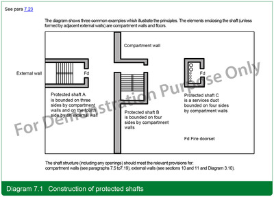
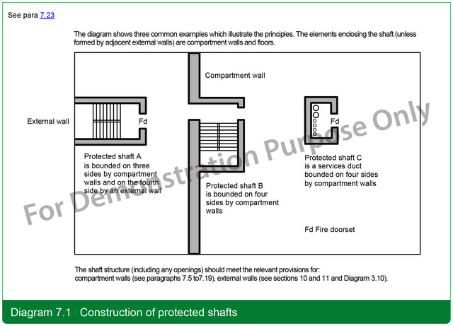
The diagram shows three common examples which illustrate the principles. The elements enclosing the shaft (unless formed by adjacent external walls) are compartment walls and floors.
The shaft structure (including any openings) should meet the relevant provisions for: compartment walls (see paragraphs 7.5 to7.19), external walls (see sections 10 and 11 and Diagram 3.10).
See para 7.23
| Item Type: | Image |
|---|---|
| Additional Information: | mml-maui-text-analytics-keywords |
| Uncontrolled Keywords: | compartment wall, external wall |
| Subjects: | Section 07: Compartmentation/sprinklers – flats B3: Internal fire spread (structure) Building standards |
| Date Deposited: | 14 Mar 2020 15:45 |
| Last Modified: | 29 Sep 2022 21:01 |
| URI: | https://buildvoc.co.uk/id/eprint/921 |
Actions (login required)

- View Item